Home » Products » Woltman Series Water Meter » Woltman meter with plastic register
-
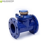
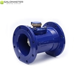
GALONMETER GL-WM-Ⅰ is TURBINE Woltaman water meter with magnetic transmission, super dry type register for Industrial and Irrigation application has the sizes from Dn40 to Dn500 designed by GALONMETER.
CHARACTERISTICS; All the materials in contact with water, consciously selected by the known resistance to corrosion; Iron body with inside and outside epoxy coating for protecting the corrosion; The ROTATING indicator register for the most comfortable reading position; The interchangeable, removable measuring mechanism can be easy removed from the body for checking, maintaining and replacing, no needs to dismantle the body form the pipe; Suitable for any position installation; Low pressure loss; No effected by external magnetic fields; Pulse output always ready, and Pulse output AS OPTION; The Pulse Output Device consists of a plastic housing with a Reed Switch, and 1,5 m cable with 2 cores in Red and Black; Electric Data: Vmax=24AC/DC; Imax=0,01A;
Capacity of the Pulse Emitter:Size
m3/pulse
Dn40 to Dn125
0.1
1
Dn150 to Dn200
1
10
Dn250 to Dn500
10
100
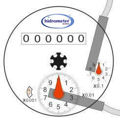
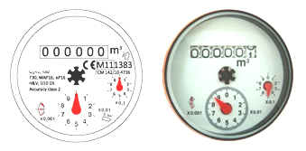
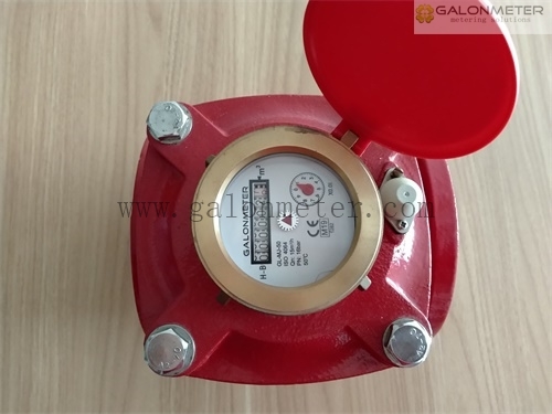
DIAL PLATE DESIGN:
DIMENSION:
The Flange Standard under ISO 7005-2:1998(E) PN16 as:Dn
40
50
65
80
100
125
150
200
250
300
350
400
500
L
260
200
200
225
250
250
300
350
450
500
500
600
800
H
225
252
262
272
282
297
341
371
480
516
560
647
785
H1
303
339
349
359
369
384
428
458
576
603
603
723
838
G
360
400
400
400
400
400
500
500
710
730
730
830
930
D
150
165
185
200
220
250
285
340
405
460
520
580
715
D1
110
125
145
160
180
210
240
295
355
410
470
525
650
nxM
4xM16
8xM16
8xM20
12xM20
12xM24
16xM24
16xM27
20xM30
*Different Flange Standard for selecting such as: ISO 7005-2: 1998(E) PN10, ASME B16.1-Class 125 working for B16.5-Class 150…
*Different Length of the Body as option:DN
40
50
65
80
100
125
150
200
250
300
350
400
500
L
X
250
250
200
300
X
430
X
X
X
X
500
500
X
270
260
270
360
X
X
X
X
X
X
X
X
X
310
X
300
483
X
X
X
X
X
X
X
X
X
X
X
413
X
X
X
X
X
X
X
X
X
MAIN TECHNICAL DATE:
Size
mm
40
50
65
80
100
125
150
200
250
300
350
400
500
R=Q3/Q1
50
80
Q4
m3/h
31,325
50
78,75
78,75
125
200
312,5
500
787,5
1250
1250
2000
3125
Q3
m3/h
25
40
63
63
100
160
250
400
630
1000
1000
1600
2500
Q2
m3/h
0,8
0,8
1,26
1,26
2
3.2
5
8
12,6
20
20
32
50
Q1
m3/h
0,5
0,5
0,7875
0,7875
1,25
2
3,125
5
7,875
12,5
12,5
20
31,25
Max.Reading
m3
999999,999
9999999,99
99999999,9
Min.Reading
m3
0,0005
0,005
0,05
PressureLoss
ΔP
10
16
10
10
10
16
10
10
10
10
10
10
10
Max.Pressure
MAP
MAP16
Max.Temperate
℃
T30 or T50
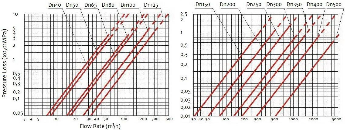
PRESSURE LOSS CURVE:
Max. Permission Error:
From Q1 inclusive up to but excluding Q2 is ± 5%;
From Q2 inclusive up to and including Q4 is ± 2% for T30 and ± 3% for T50;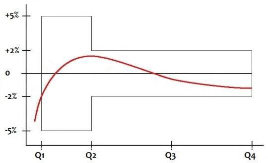
-

