Home » Products » Heat Meter » Multi jet heat meter
-
Application
For measuring the heat which, in a heat-exchange circuit, is absorbed or given up by water called the heat-conveying liquid.
Application in household-based heating system and air conditioner cooling system.
Construction
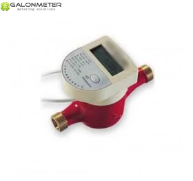
The compact head meter consists of a flow sensor, a temperature sensor and a calculator.
Features
Wi th external regulating device.
The calculator displays all actual and fixed date related data ergonomically operated by one push button.
The calculator can rotate 360°, can taken off from the meter for easily reading in any position.The flovsensor sensor measures the flow rater of the hot water passing through the heat exchange system and transfer the result to the calculator by pulse.The temperature sensor measures inlet temperature and outlet temperature of the heat exchange system. Calculate formula:
Q : The heat which is absorbed or given up in a heat-exchange circuit.
r: Density of the hot water.
V : Volume of the hot water through the heat exchange system.
h: Enthalpy difference under the condition of inlet temperature and outlet temperature of the heat exchange system.
Dimensions and WeightsNomi nal diame ter
DN
15
20
25
Body thread
D
G3/4B
G1B
G1 1/4B
Connector thread
d
R1/2
R3/4
R1
Body length
mm
L
165
130/165
165
Overall length
mm
L1
259
234/269
285
Meter height
mm
H
116
116
116
Inlet central line height
mm
H1
35
35
35
Height
mm
H2
165
165
165
Wi dth
mm
W
93
93
93
Wi dth
mm
W1
114
114
114
Weight without connectors
Kg
1.4
1.38/1.45
1.5
Weight with connectors
Kg
1.58
1.66/1.73
2.02
“L1" is the total length when coupling gaskets without compression.

Technical Data
Flow Sensor
Nomi nal diame ter
DN
15/20/25
Maximum flow rate
m3 /h
Qmax
2.0
Nominal flow rate
m3 /h
Qn
1.0
Minimum flow rate
l/h
Qmin
20
Temperature range
°C
4~95
Working pressure
bar
≤10
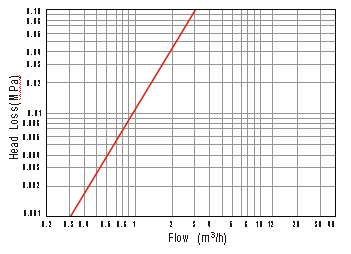
Head loss (at Qn)
bar
≤0.25
Temp erature Sensor
Nomi nal diame ter
DN
15/20/25
Technology
Pt1000
Type of connection
2-wires
Temperature range
°C
0~105
Cable length
m
1.5
Calculator

Installation
 The compact heat meter should be selected according to working flow of the heating system or air conditioner cooling system, not just the diameter of the pipeline.It is necessary to install a strainer at the inlet of the compact heat meter and clean the strainer timely.The meter must be installed with the direction of the flow as indicated by the arrow cast in the meter body. The meter where the meter is installed should apart from those insolation, pollution and frozen etc. place. A horizontal position is recommended.The compact heat meter can be installed at the inlet or outlet of heat exchange system.Wh en users order the comp act heat me ter, position of the heat me ter in the system mu st be ma rked.Hea d Loss Curve

